
EAA Wiring workshop and Great Connection
In this post, we go to EAA Aircraft Electrical Systems, Wiring and Avionics Workshop, as well as connect the rear fuselage and the center fuselage together
It has not even been a month, dear readers, and we are writing a new post! What is the reason for such frivolity? Two big events! Firstly, we attended EAA Aircraft Electrical Systems, Wiring and Avionics Workshop, which was held on Mar 26-27th in Fremont. It was super interesting – huge shoutout to Dick Koehler for the putting together amazing syllabus (and lots of cool stories). For us, it was especially timely, given that we are starting to plan the wiring and actually are doing the wiring in the rear fuselage. There is a lot covered in the course, ranging from the basics of selecting the right wires and crimping, to antennas, planning electrical system, do’s and don’ts of alternators etc. Not going to attempt to replicate everything here, will just cherry-pick a few highlights that were especially useful to us:
- when crimping splice connectors and ring terminal connectors, wire goes into the side of the crimper with the dot (crimper actually has different radius of jaws, with tighter crimp on the wire core, and less tight on insulation)
- crimping molex pins is a pain in the butt :) alignment is crucial, and it is especially hard to crimp insulation brackets without bending them in a wrong direction. It is recommended to do a few practice ones :)
- Comm antennas are supposed to be vertical or close to vertical, as radio comms use vertical polarization (in contrast, VOR/ILS antenna need to be horizontal)
- Comm antennas assume fuselage of the airplane is used as a ground plane, which means a) antenna ground should be electrically connected to fuselage b) radio ground should also be connected to the fuselage. In case of antenna mounted onto a fiberglass part (like canopy), some form of conductive ground plane must be used. We were briefly considering putting ELT antenna onto the canopy, but then decided against it.
- GPS antenna should not be placed in front of the firewall, as best GPS sattelites for triangulating position are actually at the horizon in different directions, and behind the firewall most of the view is blocked (to the front by engine, to the back – by airplane). We decided to put ours on top of the canopy (GPS antenna does not need its own grounding plane)
- Antenna cable has high losses at transponder frequency (1GHz), that’s why transponder antenna should be installed as close as possible to the panel. Also, do not stand next to transponder antenna when transponder is working!
- Alternator should always be used in a circuit with a battery. If in alternator is used without a battery (e.g. by virtue of incorrect wiring of the master switch), voltage spikes may burn avionics out
- Avionics will likely require a cooling fan
- Loose wires are a recipe for disaster
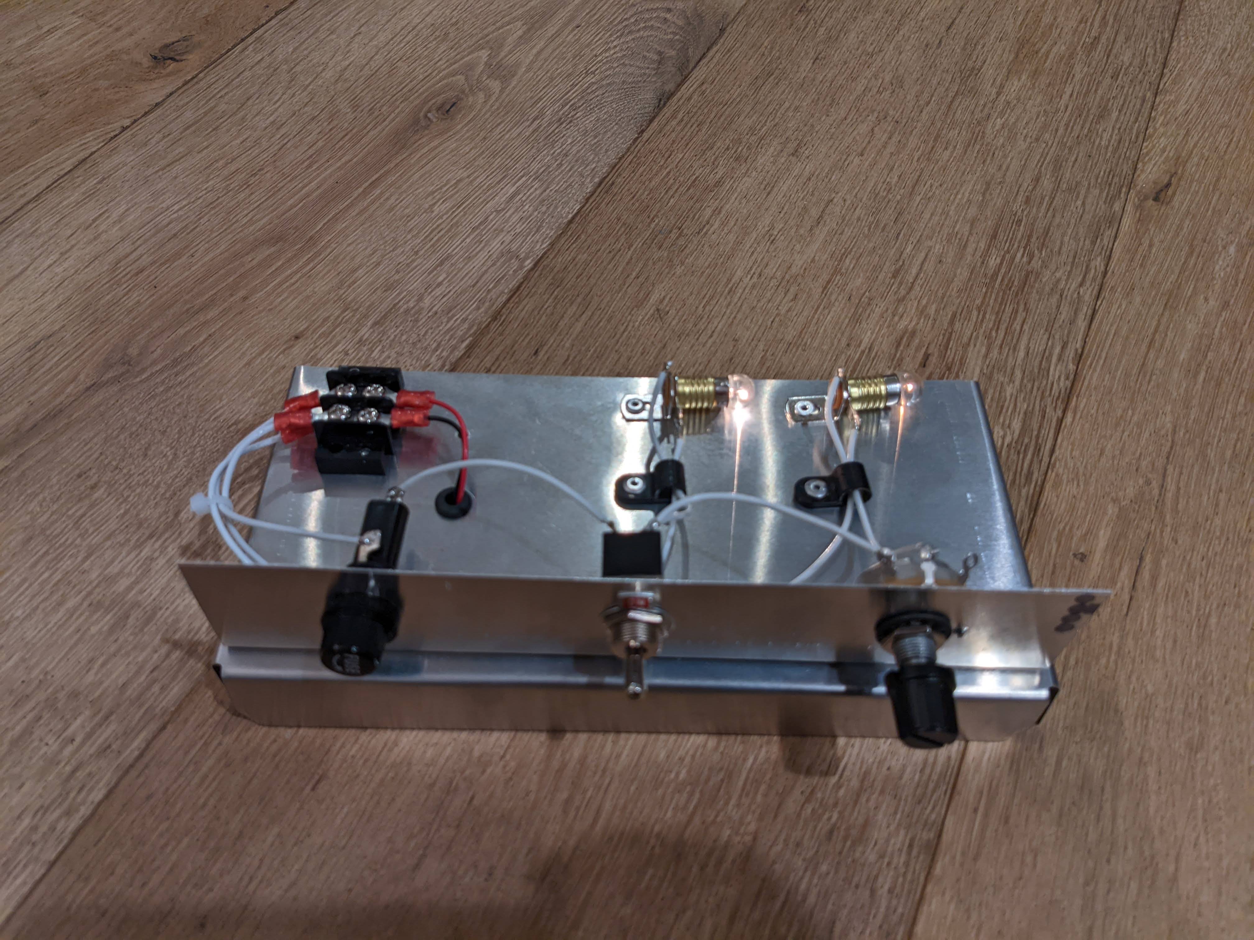
Practical exercises were also a lot of fun!
Here’s a picture of the final excercise that imitates dimmable backlighting of the panel:
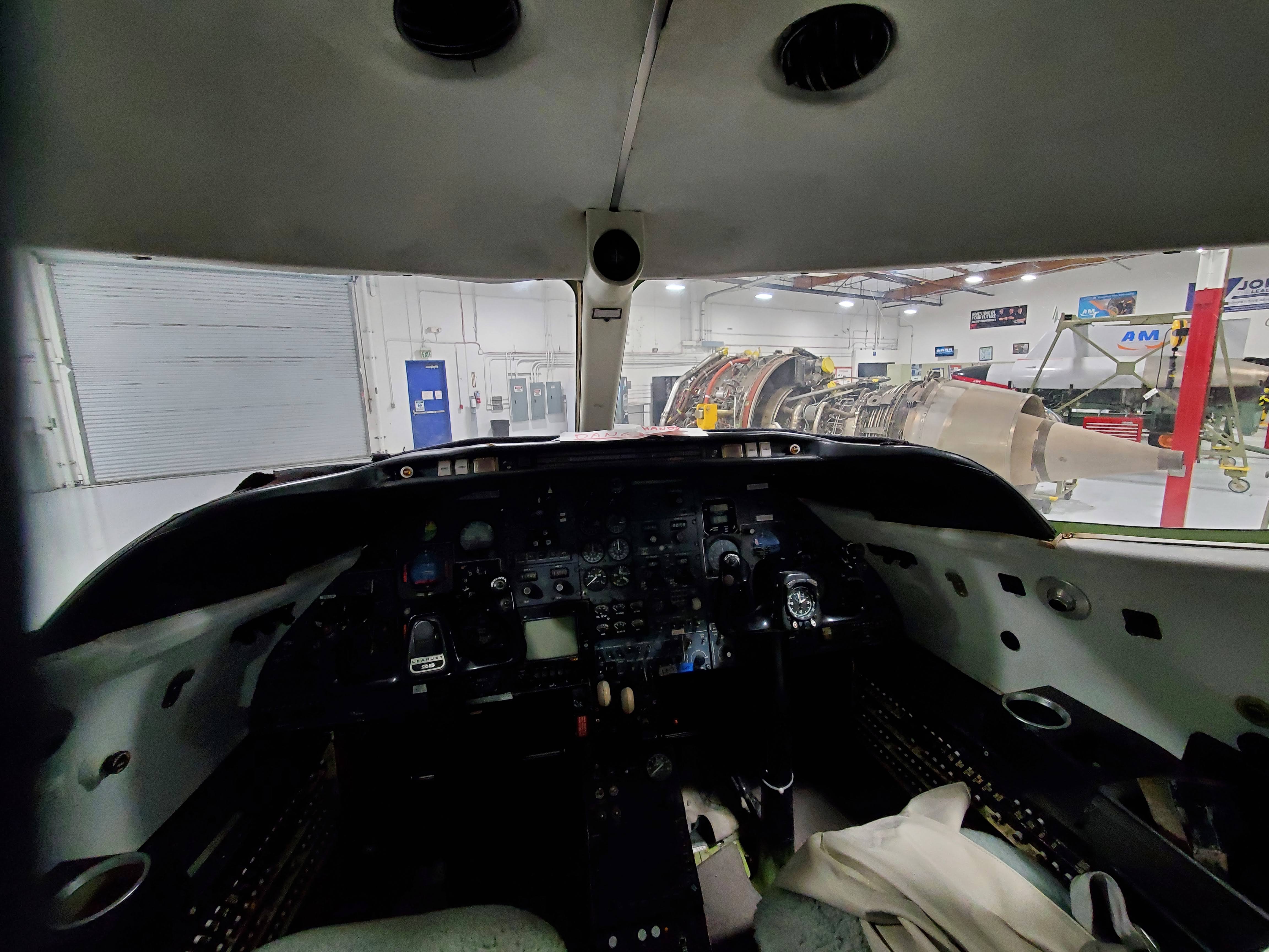
 The workshop venue, Aviation Institute of Maintenance, is also super cool! They have a bunch of airplane engines cut out and open to look and touch, so great opportunity to geek out over giant jet turbines :)
The second big event is The Great Connection! Also known as attaching rear fuselage to the center fuselage. It required some hangar reorg.
We moved the wings to the rear wall, put the one of the tables underneath the rear fuselage, and used the easels with 2x4s to support the center fuselage.
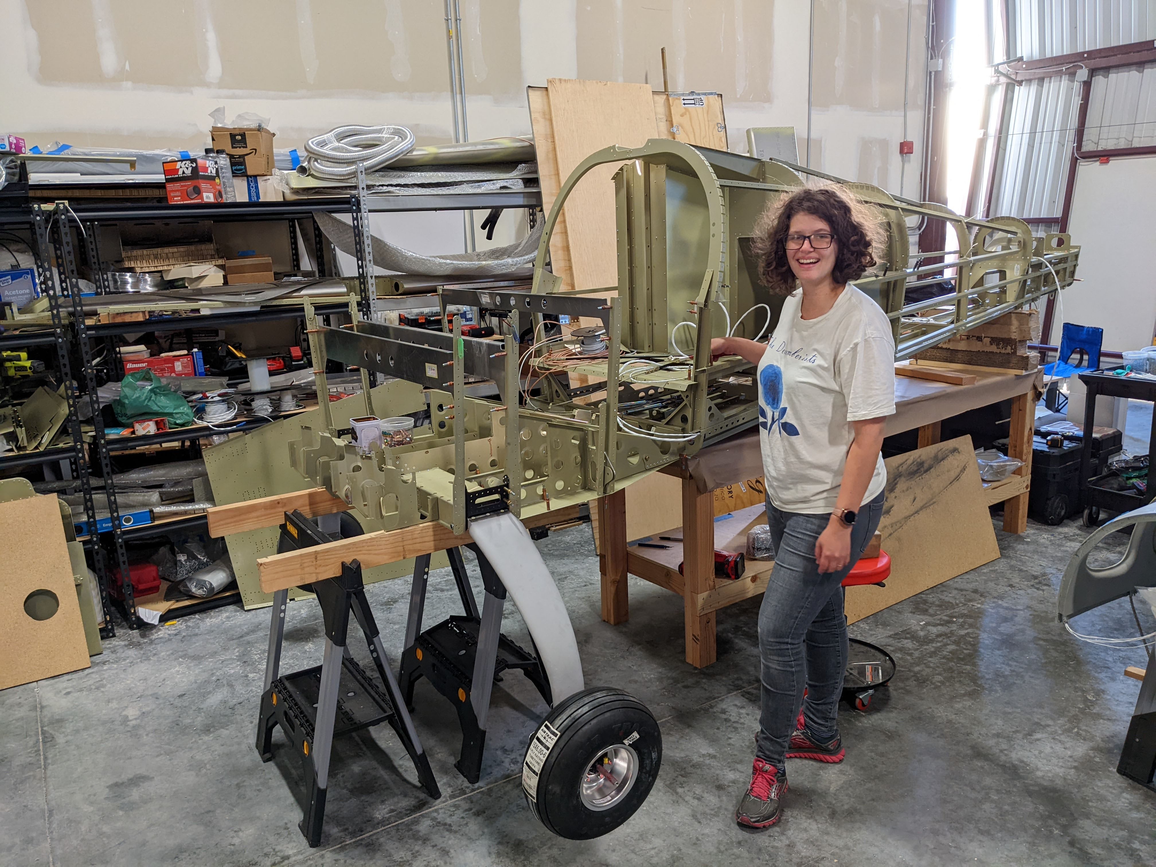
Here’s a picture of us wheeling center fuselage with the landing gear attached around the hangar:

Finally, we raised the rear fuselage according to the manual using some packaging material, and connected it to the center fuselage.
The parts fit together surprizingly well, we did not have to do much man-handling. The end result looked like this:
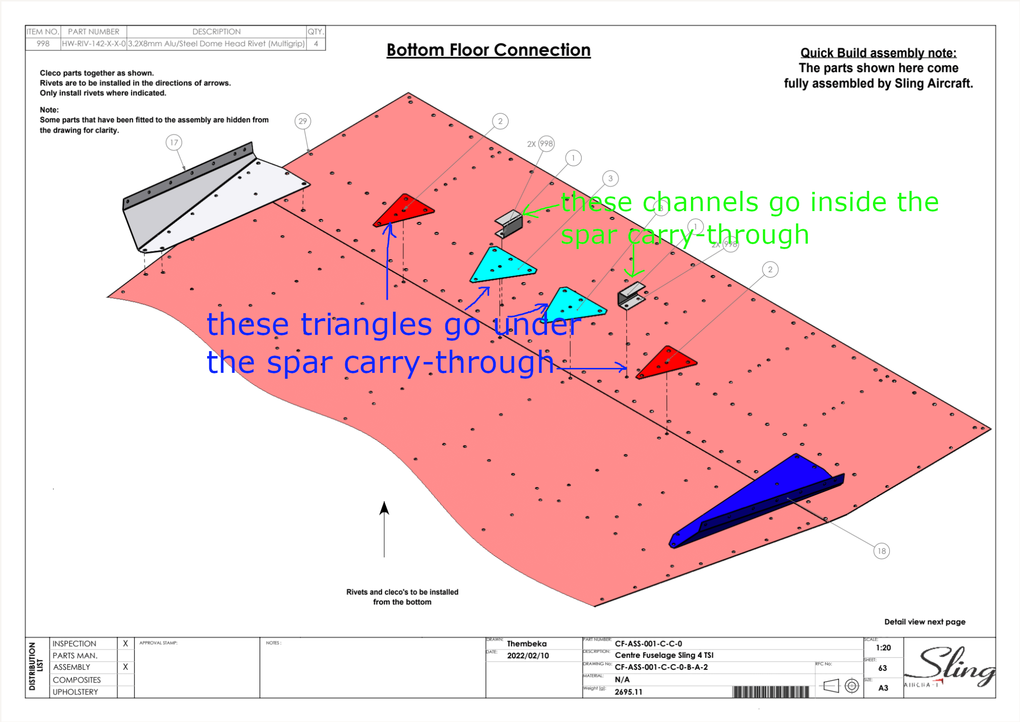
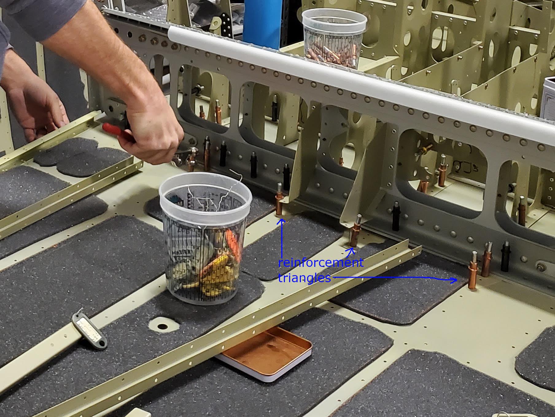
After that we attached the front part of the floor. One thing to remember is that those tiny channels shown in the manual are actually supposed to go inside the main spar carry-through
(whereas little triangular skin reinforcers go underneath the main spar carry-through).
 In this zoomed-in picture you can see the triangular reinforcers shoved between skin and the spar. One of the holes in each triangle was missing from the skin, so we had to match-drill it.
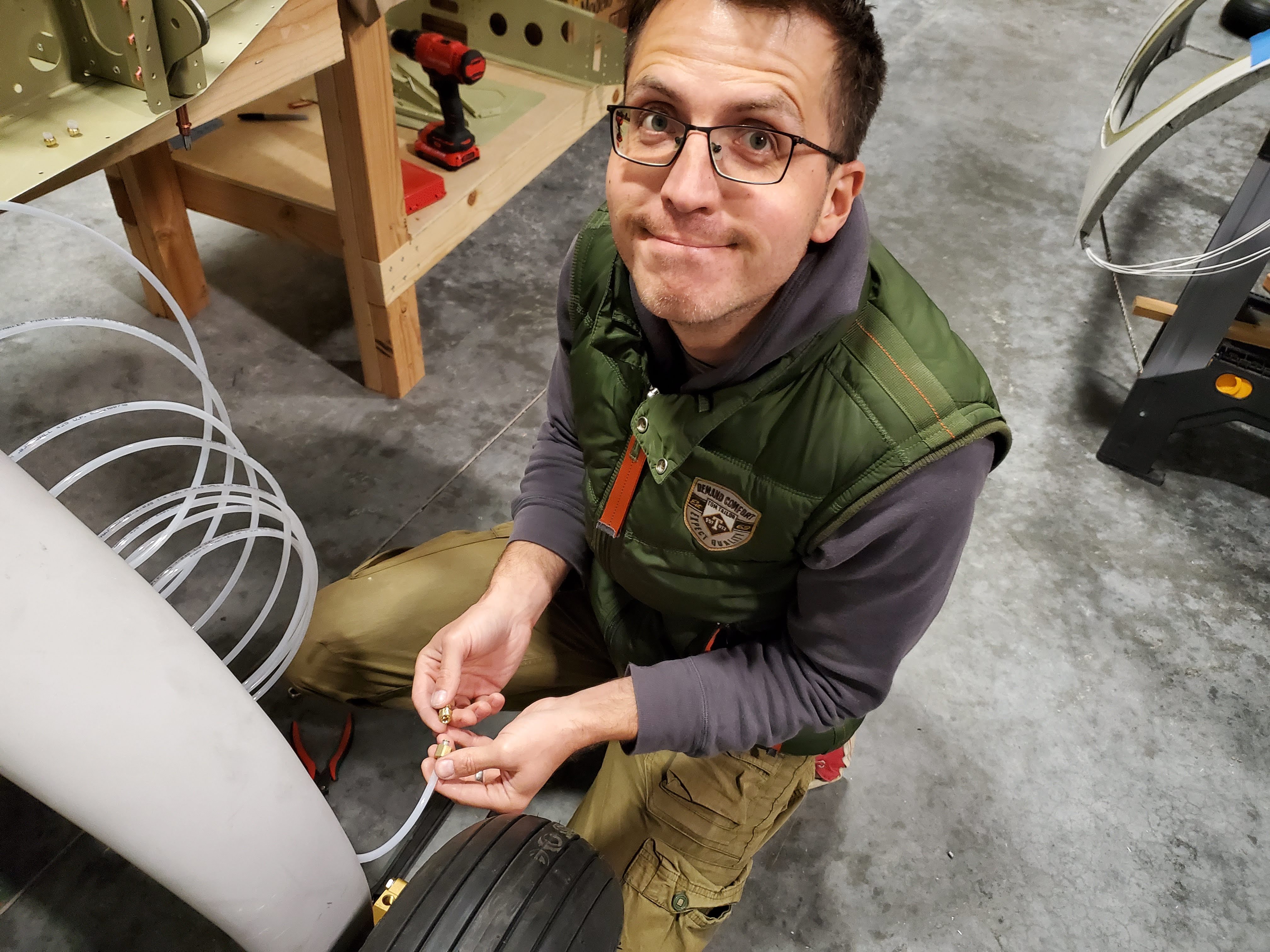
Finally, we started looking into brakes. While threading brake lines through the gear leg is pretty straightforward, however, what is not straightforward is attaching brake fittings to the nylon brake lines.
 We could not find any info online (all the forums related to nylon brake lines assumed some level of knowledge, not complete n00bs like ourselves). Eventually, by trial and error, we figured out that:
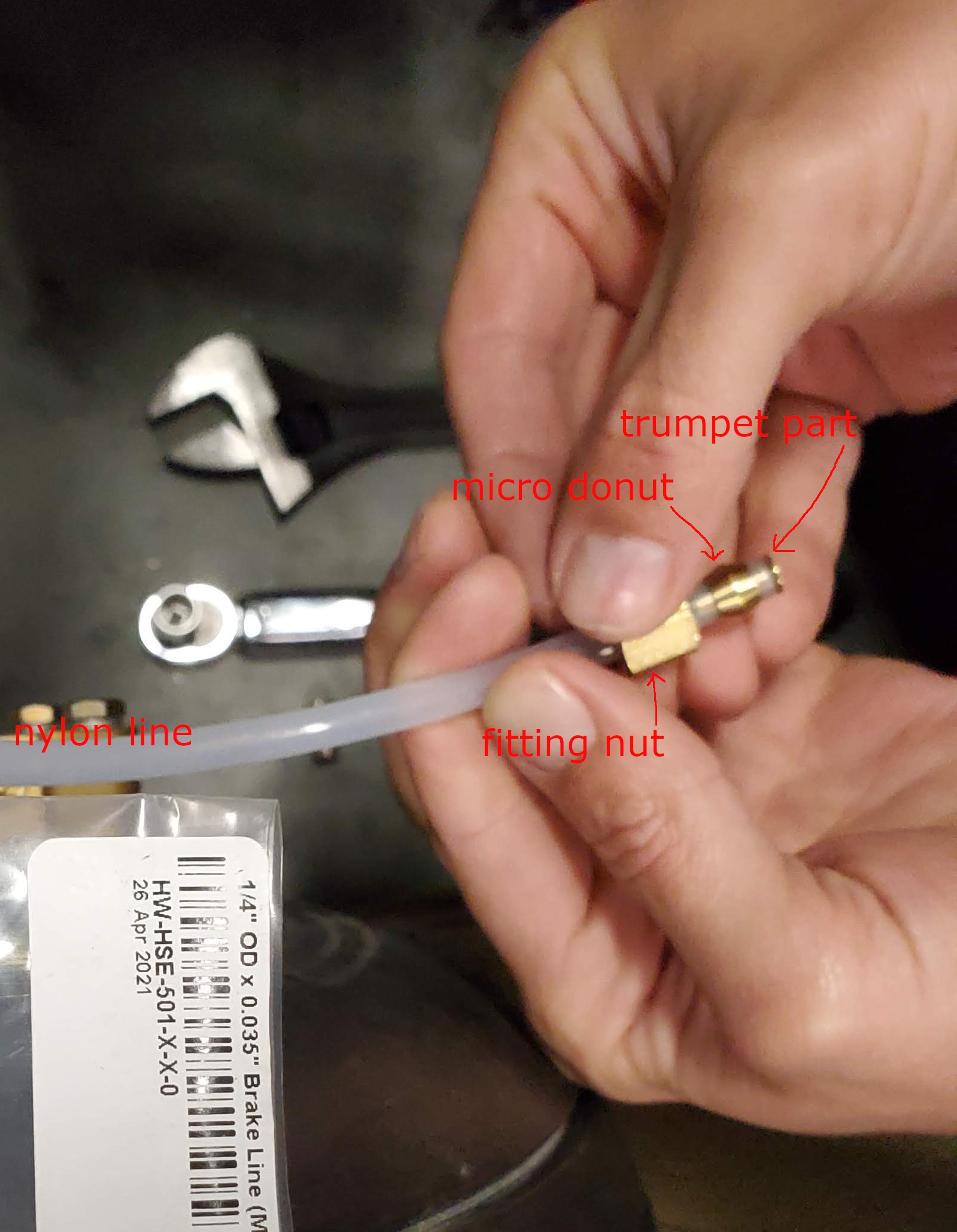
- Trumpet-shaped brass part goes inside the nylon line
- Nut (female part) of the fitting goes onto the nylon line, then
- Micro-donut shaped brass part goes onto the nylon line (and, importantly, at the very tip).
- Then one needs to carfully tighten the male and the female part of the fitting, using 7/16 in wrench for male part and 1/2 in wrench for female part, without moving the nylon line too much. As the fitting is tightened, the micro-donut looking part is press-fit into the nylon line. We found out that, if torque below 80 in-lbs is used, the trumpet part can be pried out, so we are using 80 in-lbs.
Because nylon break lines are used, and nylon does not like excessive heat, there are aluminum pipes that connect to the brakes (and nylon lines connect to the aluminum pipes). The procedure to add fittings to the aluminum pipes is the same, except there is no trumpet-like part to go inside (but the microdonut is still press-fit into the aluminum pipe; do not forget to put the nuts onto the pipe first).
Manual specifies that it is possible that we will need to re-tap some of the threads to 1/8 NPT. Evan mentioned that the only part that actually needs retapping is the parking brake valve, so, instead of re-tapping, we simply got a new parking brake valve. Another surprise for us was that a bunch of places in the brake system (master cylinder, brake calipers, park brake valve, brake fluid reservoir) use tapered thread. Apparently, one is not supposed to use a torque wrench to tighten those. Instead, a) loctite 577 need to be used to seal the threads and b) fittings are tightened to 1.5 – 3 TPFT. What is TPFT? Engineering term for “turns past finger tight” :) We tightened ours to 1.75 TPFT, we’ll see how it handles brake pressure.
#fuselage #undercarriage